Monday, 22 August 2011

Do you find Revit puzzling?

This post isn't a tip or workaround but more a simple observation which has stuck in my mind. 

During a typical working day I get lots of questions from team members regarding their Revit projects.. Some the answers I give them are quick fixes, some are simply advice tips however some are simply bad news. 

As I'm sure many of you already know, Revit can be amazing at doing complex tasks and yet sometimes it can seem almost impossible to get it to do something that the user considers a simple task. In actual fact, this is more often than not a user issue rather than a Revit issue. When this kind of thing occurs I can usually find a workaround to achieve the desired result but it often comes with bad news for the deadline panicked user.

Usually these issues are a result of a lack of forward planning when it comes to building the model or sometimes it can be a change in the user's requirements of the model. (these can be the same thing).. When this happens you often have to unpick a lot of work to be able to be able to provide a fix.. Users don't tend to like this and I often find myself the bearer of bad news.

In a recent such case and after explaining an open-heart surgery procedure for a live Revit project a colleague of mine summed up the whole thing in a nutshell. He said that it reminded him of doing a slider puzzle...


You know the one where you almost get it completed but the last two squares are the wrong way round. The only way to get it right is to go back and tear up what you have just done and rework it. Well guess what.. The same applies to your Revit projects..

Actually, I rather think a Revit Project is more like something like below but you get the idea.


I guess the lesson is to try and start with the end goal in mind. Please dont just jump in, whilst you may well get 1-13 done in record time I can guarantee you will be doing it again tomorrow if you want 14-15 the right way round.. 

Thursday, 4 August 2011

Beware of the Dimensional Rounding


This is an interesting issue i have come across on a number of projects now and therefore one i thought worth posting about. Its symptoms include not being able to dimension elements horizontally within sections. For example, your section cuts perpendicular through a wall however for some reason you cant dim to the wall edges.
To make this worse, you can see your Gridlines in section but if you try and dimension to them you get the following error message:

Crash

As the message suggests, this can be pretty serious.

This pretty much ALWAYS caused by the section not being perfectly perpendicular to the gridline. What is odd about this is the fact that Revit actually displays your gridlines even if this is true.. How can it if the view is not perpendicular? My guess is that Revit has some element of tolerance when it comes to this. The problem seems to come because the dim tools don't appear to have ANY tolerance.

So lets check the theory:

Within the file above the first thing i looked at what the relationships of the grids to each other. I threw a few dims on and it all appeared fine.

Check 01

The thing is, i have seen this a few times before so i knew what was happening here. The key is to be aware of the decimal rounding which the dim styles is applying to the angular dims in the image above.
To check I went into the dim settings via the route highlighted below:


Dimstyle -1

Initially the dim style was set to use the project settings. This was rounding to 2 decimal places.
To check the true angles of the dims i set the dim style to Degrees, Minutes and Seconds.

The results were as below:

Check 02

Oh dear..

This is the equivalent of the being 0.0001 degree out.. Seems a bit harsh doesn't it but the fact is it is incorrect.
Now the fact that the grids are not perfect is not strictly the problem here but it is the cause. In truth the crash is caused by the fact that the section is not at exactly 90 Degrees to the intersecting gridline.

Of course the correct thing to do here would be to check and adjust the gridlines and all the other geometry within the model but this is not always viable. If this error is caught early enough correcting the grids may be viable. However as is more often than not this error is not found until weeks into a project.

I guess the lesson learnt from this would be to use Degree, Minutes and Seconds as a basis for angular dims, at least for the initial project setup.

I do have a work around to ensure that sections are perfectly perpendicular to a gridline. I will try and cover this in my next post.

Wednesday, 8 June 2011

Modelling Floor Finishes–The FAST way!

Well, after a little Twitter banter between myself and David Light last night regarding modelling floor finished I appear to have spent the day trying to figure out how we can model floor finishes within our projects efficiently. I say efficiently because this is something we have tried before but found it to be pretty labour intensive and a little too similar to polylining in AutoCAD for my liking. Previous attempts of modelling floor finishes using thin floor types proved painfully slow and inflexible.. Whilst this approach did achieve its purpose of providing us modelled floor finishes it entailed endless updating when things changes such as wall build-ups. When this happened we had to modify the sketch of the floors to match the new wall face (and yet we could of locked it but i hate locking the model down too much).

The alterative to this would be use the room parameters to provide floor finish information which is ok but only gets you so far. As soon as a room contains more than one finish (which they almost always do) this method either becomes overly complicated or else breaks down completely.

So, my cunning plan is to model the floor finishes in each room like the floor type method but this time using ceilings instead of floors…. Yes, that does sound a little daft i know but honestly, I think its going to work a treat and here's why.

When using the ceiling tool, Revit has the great feature called Automatic Ceiling. This allows the user to simply click a room and the ceiling sketch will be applied to its perimeter. The best thing about this is the fact that these ceiling sketches are dynamically linked to the room’s bounding elements.

image
For some unknown reason Autodesk have not yet included this feature in the flooring tools which is why using ceilings the ceiling toolset will save you hours!.
To use this method simply create yourself some new compound ceiling types making sure you move the finish from the underside to the topside. Adjust the makeup to suit your floor types.

image
With the new (ceiling) floor type made jump to a floor plan and hit the Ceiling tool. Before you actually create the ceiling first check where you are placing it. Make sure you set the offset from level to 0 and untick Room Bounding. One big advantage using a ceiling rather than a floor is that you don't have to worry about offsets. Ceilings are set by their underside whilst floors are set by their topside.
image
Now simply add the ceiling using the Automatic Ceiling function by selecting the room. This is a really quick way of modelling floors within rooms.
If you need two finishes in room model the primary finish as above but then add the second type on top of the first ensuring the top surfaces are level. You can then user the Join Geometry tool to effectively cut the secondary finish from the primary. When doing this ensure you select the cutting object first.

image
Not only can you cut one finish out of another but you can also use the floor finishes (ceilings) to cut recesses into slabs where required. Barrier matting would be a good use of this.

Barrier Matting & Slab

image

Slab cut by Barrier Matting
image

From Revit 2011 onwards you can also take advantage of the new Realistic View settings to give you real world material representations as well as traditional hatch based views.

Hidden Line:
image

Realistic
image

As well of all the plus points highlighted above perhaps one of the most important things about this method is the fact that we can now accurately schedule out floor materials by type, hopefully putting a bit more “I” back into BIM.
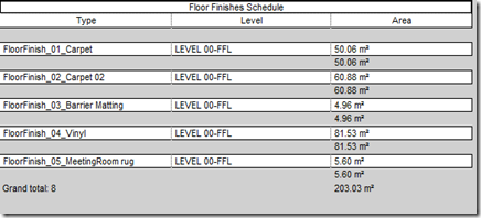
image
Its important to note that the whilst the schedule does take account of elements cutting each other it does not account for the sections of finish within the door openings. I guess you could update the sketches to pick this up once the walls and door positions are frozen if you wanted to be super accurate..

Finished product. (including a schedulable rug!)
image

All in all, I’m thinking this is a pretty good workaround, now i just have to try and persuade people at work to give it a go.

Comments welcomed.

Friday, 6 May 2011

Fake Revision Clouds in Revit

Well, I said I would post didn't I so here it is:

Ever wanted to add a revision bubble to a drawing in Revit to highlight something on a drawing but not actually add a revision to the sheets? Its one of those things that we used to do in AutoCAD but Revit seems to be almost too smart and doesn't let you do it. A good example of this would be say if you wanted to highlight something on a drawing is in abeyance. Well Revit;s detail line tools don't have a cloud option but there is a nice workaround.


  • Use the standard Revision Cloud command from the Annotate tab to sketch your cloud.

  • Before you finish the command, select all the cloud lines and copy to clipboard using the button highlighted below.

  • Now cancel the command using the red X. You will get the following dialogue box. Hit yes.


  • Now, from the Annotate tab select Detail Line, and rather than try draw the cloud simply select Paste Aligned to Current View from the Paste button drop down which is accessed via the little arrow highlighted below.

  • Hey presto, Detail Cloud lines as requested and no actual revision on the sheets. Nice.


I wish I would take credit for this but in actually fact it was my colleague sat next to me who figured this out today. Nice one Nat. :) 


Back in the Seat...

Well, its been a LONG time.. I hadn't realised just how long its been.. I suppose I have just been super busy on the work front and super lazy on the blog front but this week I was kind of shocked back into the blog world when I met a friendly gent at a BIM meeting in London. He introduced himself to me and said he recognised me from this blog...I was a little shocked but pleasantly surprised to be honest. I was beginning to think that the only person who looked at this was actually me but it would seem that I do have some viewers. So that got me thinking,, I should really make more of an effort to keep posting and building the blog.. So here I am..

So a big thank you to David Wood of Chapman Taylor for giving me the nudge I needed .

Friday, 10 December 2010

Holographic Presentation Material...Yes Please!..

I wouldn't of thought it would be too hard to get your Revit model into one of these...

Wednesday, 3 November 2010

Immaterial?

Check out this great post from Dave Baldacchino on Revit Room Materials.. A common cause of frustration when trying to deal with interior finishes.

Do U Revit?: Immaterial?

Monday, 1 November 2010

Room Object Holding Pen

Ok, this is a really simple but useful tip which came to me today at work whilst having to make some amendments to a general arrangement layout. The layout in question has a number of room objects already set out and they all contain quite a lot of data such as name, number, department as well as a few custom parameters which I tend to use in all my projects. The plan view I was working in had a colour scheme applied to it to help identify the room functions.

The changes I wanted to make would mean pretty much destroying the layouts to reconfigure the layouts. Now as I’m sure some of you will of already found this process can be messy throwing up all sorts of error messages along the way regarding the room objects not being enclosed and so on. One way of dealing with this would be to delete the rooms being changed first, make the layout updates and place the rooms again from the drop down list of rooms in the project. A second way would be to drag the rooms outside into free space, live with the error messages about them not being enclosed, update the layout and drag the rooms back into the layout again. Both of these methods would work but somehow didn't seem satisfactory to me. I needed a visual method temporarily storing and organising the room objects whilst i made the updates. So I decided to make myself a Room Holding Pen. All I did was to create a simple boxed grid object to one side of the layout using Room Separation Lines. I then dragged the rooms into the pen, updated the layout and dragged the rooms back into the layout again.

Now i know this is a real simple thing but it really seemed to make good sense to me. By using the pen to hold the rooms whilst i worked on the layout it allowed me to keep in my mind all the spaces i needed to accommodate in the new layout. It also has the added benefit of keeping the Colour Scheme fills applied to the moved rooms which wouldn't happen if i simply dragged the rooms out into free space.

So, the next step for me was to try and figure out how i can make myself a simple family or template for the holding pen so i don't have to repeat this process every time i have to make a layout update. Don't get me wrong, it doesn't take long to draw one whenever you need one but i make a lot of layout updates and i hate drawing the same thing over and over. Given that you cant make room separation lines within a family i figured the only way to do this would be as follows:

Create the grid within a blank project using Room Separation Lines.

Grid-object-01

Group the room separation lines by selecting all the lines and hitting the create group icon. (giving it a suitable name)

Create-Group

Save the group to a library location via, Save As / Library / Group

image

Finally Load into into new projects using the Insert Tab / Load As Group.

image

One in the project you’ll need to drag the group from the browser into the model environment, placing it alongside your model.

image

Next drag your rooms from the model and into the Holding Pen.

image

Rearrange your layout and drag the rooms back into the model again.

image

Again, i know this is essentially a really simple tip and I'm sure some of you out there will have your own ways of doing the same thing but it is something which i found useful in my everyday workflow and as such I hope some of you will also find it useful too.

Tuesday, 26 October 2010

How to stop Revit floor slab edges from moving.

Some of you may already know this workaround as it does go back a few years but it’s something that I have just stumbled upon which would of saved me a lot of time on previous projects.


The symptoms.
  • Having groundhog day checking and double checking your slab setting out?
  • Wondering why one edge of the slab appears to of shifted whilst the other side remains in the same location?
  • Spending days wondering who is sabotaging your slab setting out and perhaps more puzzling why someone would be doing this?
  • Getting sick of having to edit the slab sketch and YET AGAIN lock it to a gridline?

 The problem:
Floor slabs sometimes feel the need to try and be helpful by shape shifting themselves when walls which are adjacent to their edges get moved. If the wall moves the slab edge moves. You can try any of the following methods to combat this behaviour to no avail. Pinning, locking sketch edges, locking dims, isolating on separate workset...All of which won’t work.

 The solution:
Simply put the slab(s) in a group and it will no longer be able to shape shift..
A very simple but very handy workaround. I’m guessing the same thing applies to roofs and ceilings although i haven't tested it on them yet.

Monday, 4 October 2010

AEC (UK) BIM Standards for Revit

Well, Its been a long time I know so I thought I better get back on board with updating the blog..

I wanted to spread the word about the AEC (UK) BIM standards for Revit which is freely available to download from www.aecuk.wordpress.com. This document should hopefully be of interest and of use to those of you out there who are starting to think about Revit standards within your office or your Revit projects. The standard covers a wide range of common issues including:

  • Project BIM Strategy
  • Collaborative BIM Data Sharing
  • Data Segregation
  • Modelling Methodology
  • File and Folder Naming
  • Presentation Styles 

The document is intended as a guide and is open to suggestions for improvements and modifications so please feel free leave feedback on the AEC website.

Monday, 5 July 2010

Custom View / Sheet Folders

One thing that I have seen both new and experienced Revit users struggle with is trying to keep the project browser in Revit organised. On small projects this may not be an issue however on larger multi-user projects the browser can soon become a handful to deal with.There are multiple approaches to this however I favour giving the users the ability to create their own folder system within the browser. This is something I encourage all my local Revit users to adopt and so far it seems to be being well received. 

The example below is only a sample project with a few views and sheets however the you can already see how the browser may become a long meandering list with associated view/sheets becoming disjointed.


In order to tackle this you will need to add a project parameter to both the Sheets and the Views objects as per below. Group this under Identity Data


Next step is to create yourself a custom Browser Organisation to utilise the new parameter. This can be done via the User Interface drop down under the View Tab. (Far right-hand side)


Simply create a new Views Browser Organisation and give it an appropriate name. I use By Folder.


The next dialogue box controls how the browser is to organise the views. Select Group by Family & Type and then by View/Sheet Folder. 


The next step is to do the same however this time for the Sheets. Create a new Sheet Browser Organisation, give it the name By Folder.


This time you only need to group by View/Sheet Folder.


To apply the new Browser Organisations you have just created simply right click on the root of the Views/Sheets and select properties. 


Change the type to By Folder and apply.


You should now see browser looking something like below. It appears the same as before however now all the Views and Sheets appear to be in a folder labelled ???. This is the default location for any view/folder which does not contain and data in the View/Sheet Folder parameter yet.


To start creating folders simply select (or multi-select) a view and go to its element properties. Under Identity Data you should see your new parameter. Simply type the name of the folder which you would like the view(s) filing under in this field. 


You should now see the sub folder in the browser has been created and the views moved from the ??? area.


You can run through the element properties of the views/sheets in the browser however I tend to find it easier to create a Drawing List & a View List via the schedule button. Add in the parameters you would like to see including the new View/Sheet Folder parameter and enter the folder names you would like the views/sheets to have. 


The end result is a Project Browser with custom sub folders as per the example below.


Once you get your head around this it becomes quite straight forward and provided you with a very flexible system for organising the browser. The Browser Organisation system within Revit is a very powerful and flexible tool however I find that its perhaps one of Revit's least utilized functions. Perhaps this is because it is an area which may users overlook or maybe they simply learn to get by with the out the box settings, I'm not sure. What I do know is that people like the ability to customise their browsers simply because we all tend to work in differing ways. Hopefully this system provides you with a simple and flexible solution to organising a Revit project's views and sheets.

Saturday, 3 July 2010

Dividing lines & Arcs Part 2

The Second and perhaps more useful way of dividing a line into a set number of parts is to use the array command.

In this example I will be dividing an Arc but its the same principle for a straight line.

First identify the centre of the arc via its element properties. This time draw a line from the arcs centre point to one end of the arc.

With the straight line selected hit Array from the modify tab.You will need to select the button for radial array and the check-box saying Move To: Last.


Next we need to move the straight lines centre of rotation to the centre point of the arc. To do this simply click and hold the icon highlighted below and reposition.


Now you have set the rotation centre point you need to select a reference point to start the rotation. In this example select the start of the arc and rotate to the end of the arc.


You should now see something like the diagram below with a temporary dimension on the arrayed objects which is asking for the number of times the object is to be arrayed. You can input the required number directly into this temporary dim.


The results should be something like below:


The great thing about this is that if you change your mind as to how many times the object should be arrayed you can simply select one of the arrayed objects to access the temporary dim again and alter the number to suit.

Result:


This is by no means limited to lines, it can be applied to both detail and 3D families as well.


One thing to be aware of when using this method is that what you are actually doing is creating a group in the process. This is not a problem in itself however it is something you should be aware of . Having lots of groups and arrays within large projects can impact of the project's performance. This grouping behaviour is controlled within array command as highlighted below:


Having this tick box unchecked will still allow you to array the object as above however you will not be able to modify the array once its done.